DE
DE ES
ES IT
IT FR
FR RU
RUCurrently there are no products in your shopping cart!
Rudder Adjustment
Rudder Adjustment
ASSEMBLY AND ADJUSTMENT OF THE RUDDER
Gudgeon Adjustment for Compatibility with Boat Transom/Stern

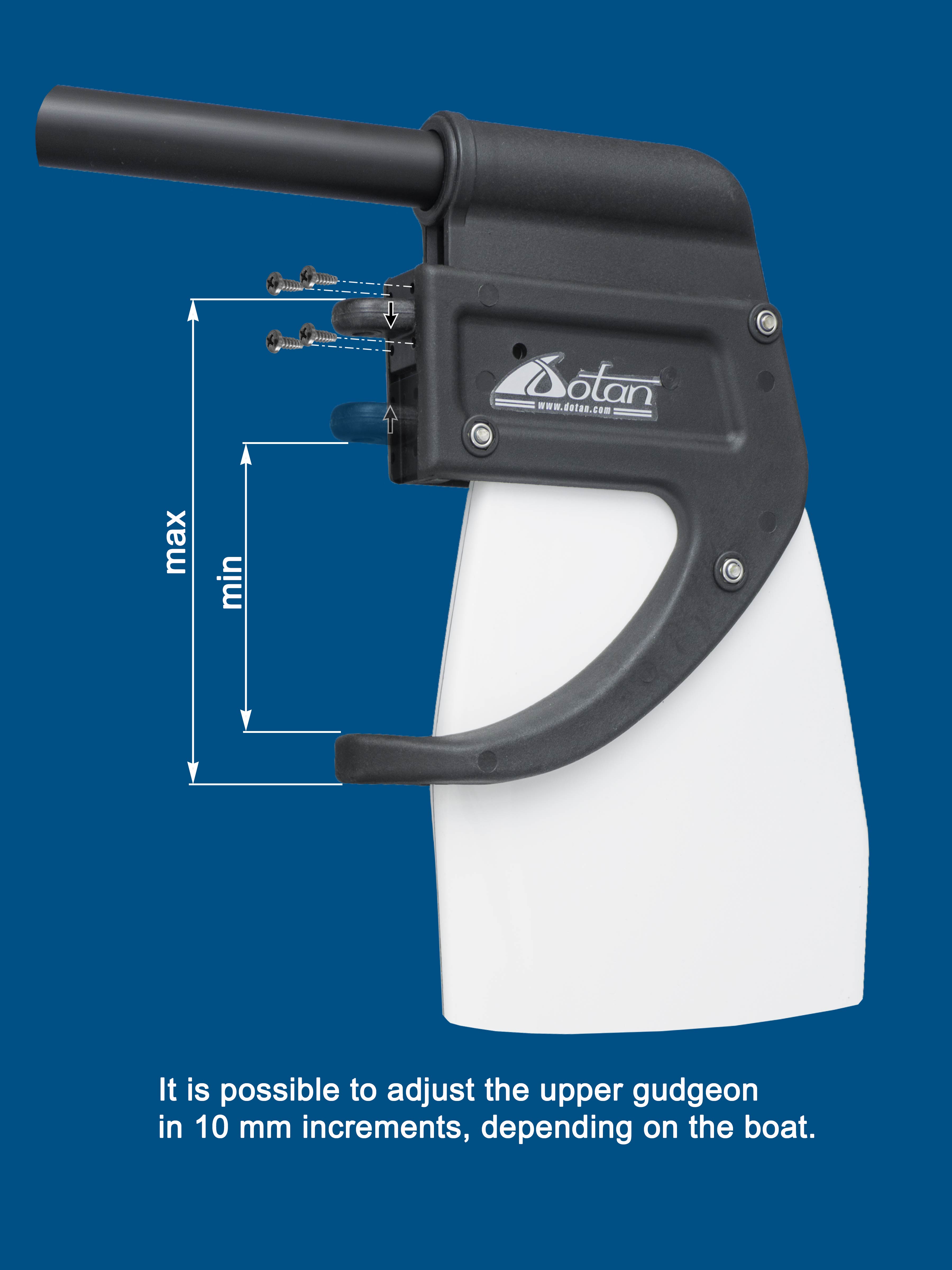
Sailors can adjust the distance between the upper and lower gudgeons, ensuring compatibility with various boat transoms and sterns. The upper gudgeon moves freely along the rudder head track. Simply position it to match your boat’s specific transom or stern dimensions and secure it in place using the four supplied screws.
Options for rudder installation with holes in the gudgeons.
Variants of a rudder setting with pintles in the gudgeons.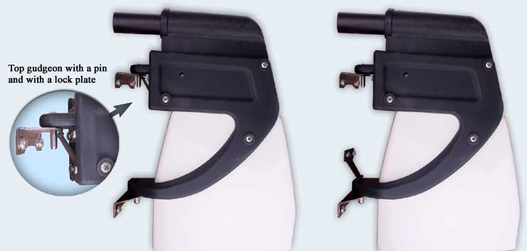
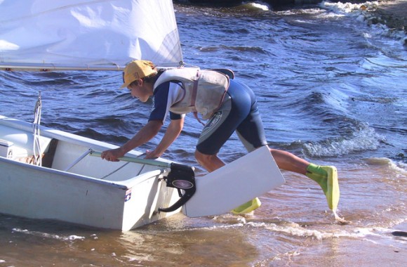
When installing the rudder on the boat's transom, ensure free rotation.

The rudder head track must not rest on the transom gudgeons or any other part of the transom.

The rudder head may touch the transom with its side surface or rest on the transom with its lower part.
Rudder Blade Angle Adjustment
The rudder blade angle can be adjusted by changing the length of the coulisse. The length is adjusted by rotating the coulisse nut relative to the coulisse bolt. For example, turning the coulisse nut one full revolution changes the blade angle by β = 2.1° from vertical. The maximum adjustment of β = 16.8° is achieved with eight full turns of the nut.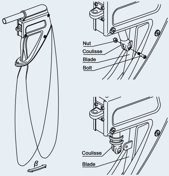
Adjustment of Pressure for Rudder Blade Release upon Collision with Underwater Obstacles
You can easily adjust the rudder to lift at different pressure levels upon collision with underwater obstacles (such as ground, seabed, etc.) by changing the position of the silicone pusher located inside the rudder head. The rudder is supplied with the pusher set in the default middle position (see Fig. b below). The blade fixation can be increased or decreased by 25% if needed.

Adjustment Procedure:
- Disconnect the coulisse from the blade by unscrewing the M5 bolt.
- Lift the tiller housing.
- Remove the lock by unscrewing the M6 bolt.
- Place the silicone pusher in one of the three positions: a, b, c (see diagram below).
- Reassemble the rudder in reverse order:
- Install the lock and secure it with the M6 bolt.
- Lower the tiller housing.
- Attach the coulisse to the blade by tightening the M5 bolt.
Important: Ensure that the set pressure for rudder lifting meets your requirements.
Silicone Pusher Positions for Three Rudder Release Pressure Levels
.jpg?1493130326450) |
.jpg?1493130340128) |
.jpg?1493130348414) |
||
| Upper position of the pusher – maximum rudder blade fixation. | Middle position of the pusher – medium rudder blade fixation. | Lower position of the pusher – minimum rudder blade fixation. |
Rudder Blade Lift Locking Mechanism
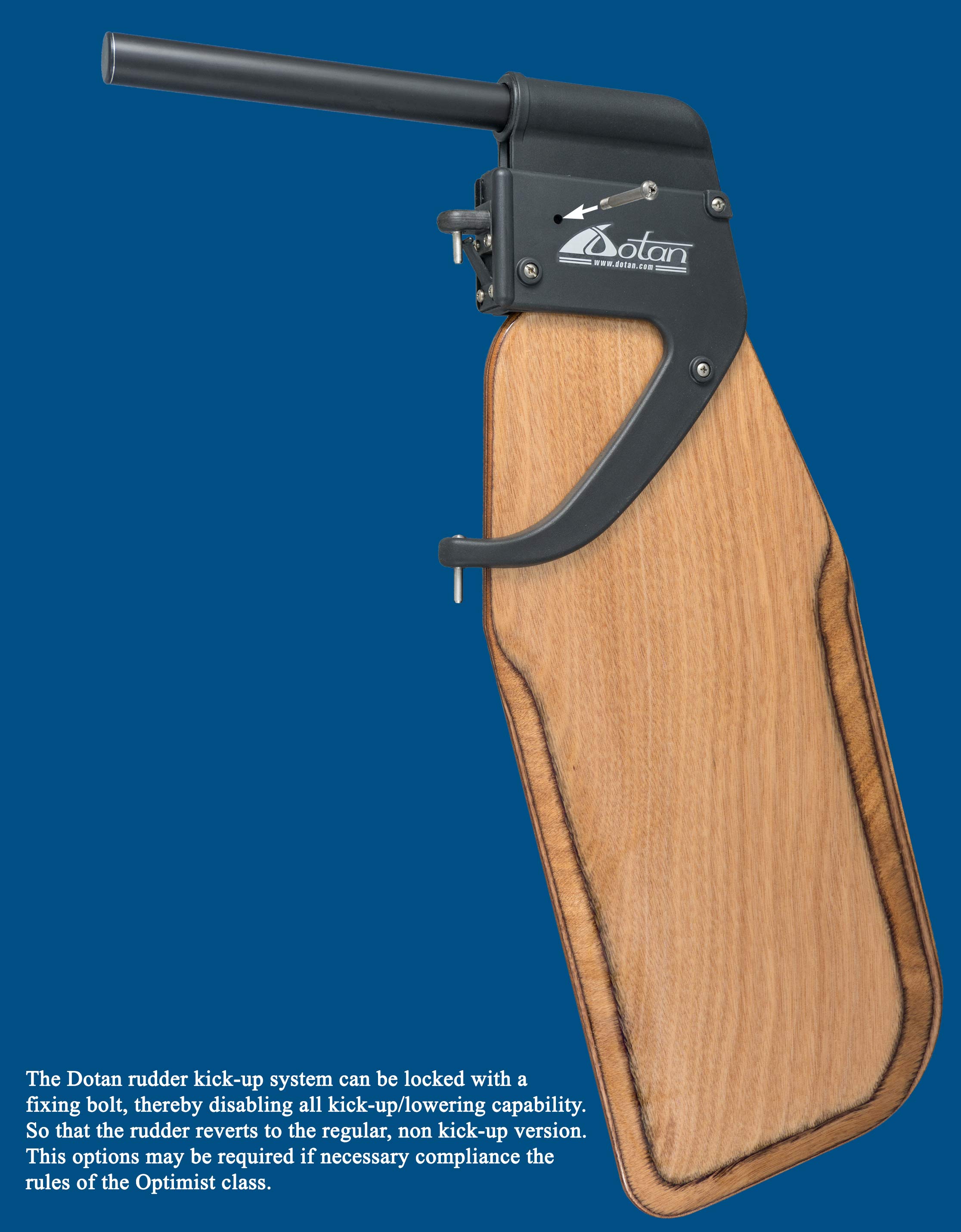
The rudder blade lift function can be disabled using an additional locking feature. A locking pin can be inserted into the rudder head lock hole, securing the blade in the upper or lower position, thus completely preventing any lifting or lowering.
Important! If you use the locking feature, do not forget to remove the pin when approaching the shore to allow the rudder blade to lift upon collision with an obstacle.
It is recommended to use the rudder locking feature in the following situations:
- To comply with Optimist class regulations.
- To prevent accidental blade lifting in deep water.
- In areas with a high presence of jellyfish.
- In challenging weather conditions.
- When the rudder system is used by a beginner.
- During boat transportation on a trailer/trolley with the blade lifted (no need for ropes).
RELATED PRODUCTS


.")


Vorteile des Dotan-Ruders
Instant Rudder Control
The Dotan kick-up system allows the blade to be raised or lowered in seconds with a single movement. Essential for smooth departures and returns, even in challenging conditions.
Durable Housing
Made from corrosion-resistant composite materials, the rudder housing ensures reliability and stability, even in extreme situations.
Lightweight and Strong Blade
Combining advanced thermal shock technology and high pressure, the blade offers reduced weight and excellent durability. A hydrodynamic profile ensures smooth sailing.
Universal Adjustment
Easily adaptable to various boats and catamarans, the rudder’s simple installation makes it suitable for users of all experience levels.
Obstacle Protection
The blade automatically kicks up upon collision with obstacles like rocks or logs, preventing damage. It returns to position in seconds, maintaining control and stability.
Why Choose Kick-Up Rudders from Dotan?
Learn more about the Dotan rudder mechanism
SHOP NOW